- 您现在的位置:买卖IC网 > Sheet目录364 > SSL3250AHN/C1,528 (NXP Semiconductors)IC LED DRVR PHOTO FLASH 16-HVQFN
�� �
�
�NXP� Semiconductors�
�SSL3250A�
�Photo� flash� dual� LED� driver�
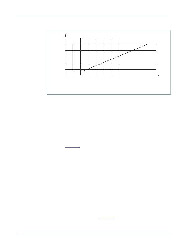
�600�
�I� LED� (mA)�
�500�
�400�
�300�
�200�
�100�
�70�
�0�
�357�
�125�
�Flash� current� using� direct� control� mode�
�50�
�Resistor�
�Value� (k� Ω� )�
�014aaa367�
�Fig� 8.�
�Flash� mode� LED� current� in� Direct� enable� mode�
�8.3.5� Timed� Flash� mode�
�The� timed� operation� of� the� Flash� mode� can� only� be� used� in� the� I� 2� C� interface� mode.� When�
�the� flash� is� used� in� Timed� mode� (bit� 4,� TO_DEF� =� 1� in� Timer� control� register� 01h),� the�
�internal� timer� will� switch� off� the� main� LED� after� the� preprogrammed� maximum� time� in� the�
�timer� control� register� has� expired.�
�The� timer� starts� when� the� Flash� mode� is� activated� either� by� the� software� strobe�
�(FLASH_STRB� bit� in� register� 02h)� or� by� a� LOW� to� HIGH� transition� of� the� hardware� strobe�
�(STRB� pin)� signal.�
�In� timed� mode� strobing� of� the� flash� is� edge� sensitive,� therefore� the� flash� time� is�
�independent� of� the� level� of� the� software� or� hardware� strobe� signal.� The� flash� time� is� set�
�according� to� Equation 5� :�
�t� flash� =� 820� ms� –� Register� ×� 54.6� ms�
�(5)�
�Once� the� Flash� time� has� expired� no� interrupt� will� be� generated� nor� will� it� be� flagged� in� the�
�status� register.� A� new� flash� period� can� be� started� immediately� after� the� previous� timed�
�flash� period� has� expired.�
�8.3.6� Flash� mode� during� RF� transmit�
�Although� the� driver� is� not� equipped� with� a� separate� TXMASK� pin,� the� device� can� operate�
�like� that� to� lower� the� current� in� the� main� LED� in� Flash� mode� during� an� RF� transmission� in�
�a� mobile� phone� application.� An� external� switch� can� be� connected� to� the� resistor�
�controlling� the� nominal� current� value� for� the� Flash� mode.� By� lowering� the� current� in� the�
�main� LED,� the� inductor� current� and� therefore� the� current� drawn� from� the� battery� will� be�
�lowered.� Reducing� the� inductor� current� has� to� be� fast� because� the� inductor� current� is�
�reduced� within� 50� μ� s� after� changing� the� nominal� current� level� to� a� lower� setting.� At� the� end�
�of� the� transmission� period,� the� main� LED� current� can� be� increased� again� to� the� nominal�
�current� level.� A� soft� start� circuit� will� increase� the� inductor� current� with� a� limited� slope� as�
�defined� by� the� soft� start� settings.� See� Section 8.5� .�
�SSL3250A_5�
�?� NXP� B.V.� 2009.� All� rights� reserved.�
�Product� data� sheet�
�Rev.� 05� —� 16� December� 2009�
�10� of� 26�
�发布紧急采购,3分钟左右您将得到回复。
相关PDF资料
SST25LF020A-33-4C-QAE-T
IC FLASH SER 2MB 33HZ SPI 8WSON
SST25VF010A-33-4I-QAE-T
IC FLASH SER 1MB 33MHZ SPI 8WSON
SST25VF016B-50-4C-S2AF-T
IC FLASH SER 16M 50MHZ SPI 8SOIC
SST25VF020-20-4C-QAE-T
IC FLASH SER 2MB 20MHZ SPI 8WSON
SST25VF020B-80-4C-QAE-T
IC FLASH SER 2MB 80MHZ SPI 8WSON
SST25VF032B-66-4I-S2AF
IC FLASH SER 32M 66MHZ SPI 8SOIC
SST25VF040B-50-4C-ZAE
IC FLASH SER 4MB 80MHZ SPI 8CSP
SST25VF040B-80-4I-QAE
IC FLASH SER 4MB 80MHZ SPI 8WSON
相关代理商/技术参数
SSL3252
制造商:PHILIPS 制造商全称:NXP Semiconductors 功能描述:Smart, simple solutions for the 12 most common design concerns
SSL3252UK/C2,515
功能描述:LED照明驱动器 Photo flash LED driver RoHS:否 制造商:STMicroelectronics 输入电压:11.5 V to 23 V 工作频率: 最大电源电流:1.7 mA 输出电流: 最大工作温度: 安装风格:SMD/SMT 封装 / 箱体:SO-16N
SSL33
功能描述:肖特基二极管与整流器 Low VF 3Amp 30v SMD Schottky Rect RoHS:否 制造商:Skyworks Solutions, Inc. 产品:Schottky Diodes 峰值反向电压:2 V 正向连续电流:50 mA 最大浪涌电流: 配置:Crossover Quad 恢复时间: 正向电压下降:370 mV 最大反向漏泄电流: 最大功率耗散:75 mW 工作温度范围:- 65 C to + 150 C 安装风格:SMD/SMT 封装 / 箱体:SOT-143 封装:Reel
SSL33 R6
制造商:SKMI/Taiwan 功能描述:Diode Schottky 30V 3A 2-Pin SMC T/R
SSL34
功能描述:肖特基二极管与整流器 Low VF 3Amp 40v SMD Schottky Rect RoHS:否 制造商:Skyworks Solutions, Inc. 产品:Schottky Diodes 峰值反向电压:2 V 正向连续电流:50 mA 最大浪涌电流: 配置:Crossover Quad 恢复时间: 正向电压下降:370 mV 最大反向漏泄电流: 最大功率耗散:75 mW 工作温度范围:- 65 C to + 150 C 安装风格:SMD/SMT 封装 / 箱体:SOT-143 封装:Reel
SSL34 R6
制造商:SKMI/Taiwan 功能描述:Diode Schottky 40V 3A 2-Pin SMC T/R
SSL3401HN/1Y
制造商:NXP Semiconductors 功能描述:SSL3401HN/HVQFN32/REEL13DP//1 - Tape and Reel
SS-L3TQ100-SXA
制造商:Microsemi Corporation 功能描述:EXTENDER FOR A54SX32A-FTQ100 - Trays